Geog 495:GIS database design
10/13/05
Drawing Crow’s foot model with Visio
From the lab on Wednesday, please get this (of course in hand-written form).
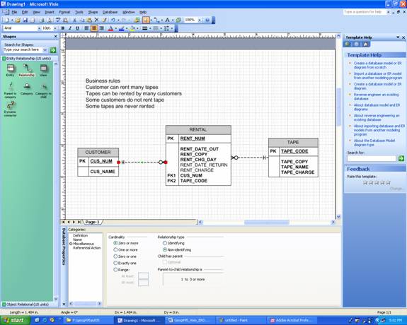
Starting Visio
Professional and Setting the stage for Crow’s foot model
Start-All Programs-Microsoft Office-Microsoft Office Visio 2003
Choose Database in the header Category (in the left) under Choose Drawing Type
Choose Database Model Diagram (US units)
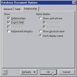
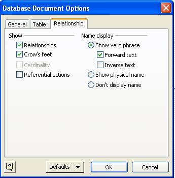
In the menu, choose Database-Option-Document
In the Database Document Options, choose the tab Relationship: Check Crow’s feet
(see below for image)
Creating an entity
Click an Entity object in the left, and drag it to the grid
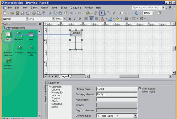
Name entity
In the Database Properties at the bottom, make sure arrow is next to Definition under Categories header, change the name to CUSTOMER while table1 is selected
Define entity attributes (columns)
Choose Columns under Categories header, type in attribute name: CUS_NUM in Physical Name. Select the TEXT option from the drop-down list under the Data Type header. Since this is primary key, check PK box. Type in CUS_LNAME and check Req’d (required).Required attributes is shown in bold face. You don’t have to specify FK because creating relationships will do this automatically in Visio.
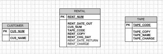
Add other entities (TAPE, RENTAL) in the similar way. Make sure PK is properly specified and all attributes are required except for RENT_DATE_RETURN and RENT_CHARGE in Entity RENTAL
You can check data type of each attribute in Microsoft Access; open Ch04_Rental.mdb file at P:\geog495aut05. In the Tables, click right mouse button while selecting table (one-click), then choose design view. (To save time, do not set data type in this lab; just stick with the default).
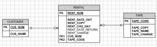
Now Visio document should look like this:
Defining relationships
Matching connectivity
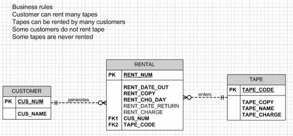
Click a Relationship object, and drag it to the grid. Note that the symbols at the two ends of the relationship line reflect default cardinalities of (1,1) and (0,N). Remember that the relationship between CUSTOMER and RENTAL is one to many (i.e. CUSTOMER generates many RENTALs). Therefore, CUSTOMER represents the “one” side of the relationship and the RENTALS represents the “many” side of the relationship.
Attach the “1”side of the relationship line to the CUSTOMER entity by dragging the “1” end of the relationship line to the CUSTOMER ENTITY. Please note that the relationship is not attached until the CUSTOMER table is outlined in red! (you may have to drag the relationship line’s end all the way to the inside of the table before the red outline shows up).When you release the relationship line, its attachment is verified by the red square on the entity (table) perimeter.
Editing cardinality/participation
Visio created the CUS_NUM foreign key in the Rental table, labeling it FK1. Note that CUS_NUM in the RENTAL table is not in boldface type. This lack of boldface indicates that, at this point, you have not yet specified that a FK value is mandatory. (Of course it should be, because a RENTAL cannot exist without a CUSTOMER. In other words, CUSTOMER is mandatory to RENTAL). How do you eliminate small circle next to CUSTOMER which is not correct?
Before 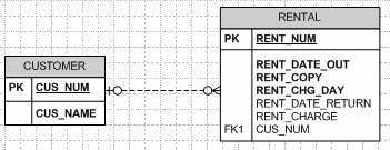
Edit FK property by checking Req’d for FK1 in the RENTAL table. Then it would look like this. Note small circle next to CUSTOMER disappears because CUSTOMER is mandatory to RENTAL.
After 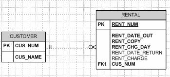
Enforcing Req’d of foreign key in M-side table allows you to edit the participation of CUSTOMER (from optional to mandatory). What about the participation of RENTAL?
Do the same (connectivity and cardinality) for the relationship between TAPE and RENTAL.
You can edit the participation/cardinality of M-side even though (0,N) is default. Choose Miscellaneous while the Relationship line is selected. Zero or more is the default as you can see below.
See how diagram changes if you choose One or more. (1,N) implies that RENTAL is mandatory to CUSTOMER, thus small circle next to RENTAL disappears.
Selecting relationship strength
Click any of relationship line. Go to Miscellaneous – choose Identifying under Relationship type (right to Cardinality). See how things change. Dashed line becomes solid line because its relationship is strong (or identifying). Also note how primary key is set to RENTAL, changing from RENT_NUM to CUS_NUM + TAPE_CODE.
Naming the relationships
Click any of relationship line. Go to Name, and type in appropriate texts in Verb phrase and Inverse phrase. Active verbs are used to label relationship from the “1” to the “M” side. Passive verbs are used to label relationships from the “M” to the “1” side. Unlike Entity and Entity attributes, relationship names are written in lowercase.
By default, relationship name is not shown. You can change this setting by choosing Database-Options-Document and checking Show verb phase under Relationship tab.
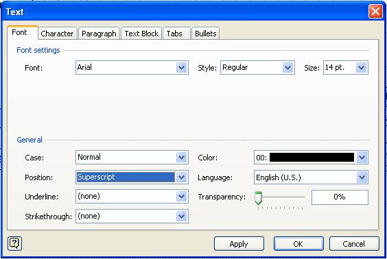
You can also change the placement of relationship name by clicking right mouse while selecting relationship line: format-text-position (to Superscript for example). Change the size also.
To place texts in the grid, use text tool ![]() in the toolbar to place writing. Use pointer
tool
in the toolbar to place writing. Use pointer
tool ![]() to move the location.
to move the location.

-- The End ---