Lab6 of Geo520, Spring 2005
TA : Julie Hwang
Lab 6. Working with Networks II
Objectives
In this lab, centroid connectors are introduced as a way to allow for routing between nodes which are not directly connected to the network. We are also working on how to set up one-way restriction to the network.
Centroid Connectors
So far we
have found the best route from node to node. But in the real application, as shown
in the figure below, we often need to find the best route between origin and
destination which are not connected to nodes in the physical networks. (Eg. city-to-city distance matrix).
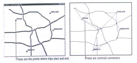
The links
that connect centroids to the other links in a network
are known as centroid connectors. These
centroid connectors are not physical links, but instead are a simplified representation of the
local road network that let individuals access the highway network (i.e. logical links).
Practice #1: Create centroid connectors
In this practice, you will be creating centroid connectors which connect city centroids
to highway.
Centroid connectors![]()
 à
à 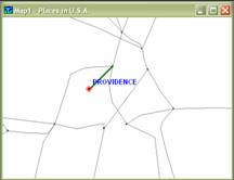
______Copy the directory H:\GEO520\Lab6\Practice
to your home directory. The directory contains standard geographic files.
You can only create centroid connectors from standard
geographic files, which is editable.
______ Open the geographic files NES_MCT and NES_HWY
from the directory you just copied.
______ Show the hidden node layer associated with
the Highway layer.
______ Open the dataviews
of CDF Node Layer. Then add a new field named Place_ID
(integer, 10) (Dataviews-Modify Tables…-Add
Field button). Click Yes when the Confirm dialog
box is prompted. Go back to a map window.
______ Display the Place layer in a different style
such that they can be distinguished from the node layer. Label them by their
name if necessary.
______ Make the Place an active layer. You are going
to create centroid connectors from this active layer to highway layer.
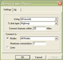
______ Choose Tools-Map Editing-Connect…
______
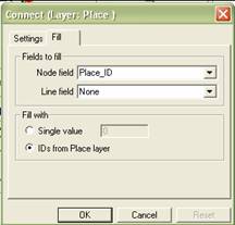
______ Click the Fill tab. Choose Place_ID from Node field drop-down list, and check the IDs
from Place layer under Fill with. (By doing so, you are writing IDs from Place layer
to the field Place_ID in the node layer). Click OK.
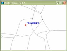
______ Zoom into any feature of Place layer. Check
to see if the centroid connectors are created.
______ Look into the dataviews
of the CDF Node Layer. Scroll all the way down to the bottom. Notice that 9 new
records are added to the node layer with the Place_ID
updated. The value of Place_ID corresponds to the ID
from the Place layer. The Highway (link) layer has been updated also.
Practice #2 Update selected records in dataviews
______ Open the dataviews
of the Highway layer.
______ Select the cells of the last 9 records in the
field [Travel Time]. Then click the right mouse button. Choose Fill… in
the menu.
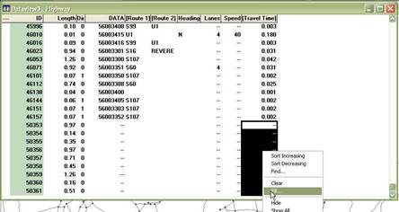
______ Choose the Formula, then type in Length /
30 in the input box. (We will assume the speed is 30 mph in the connectors)
Click OK until you go back to the dataviews. Now the
[Travel Time] of the centroid connectors have been
updated.
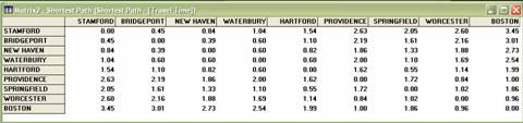
Practice #3 Label travel time matrix by a city name
You will
be creating travel time matrix (or multiple paths) as you did in the previous
assignment. But this time you will be making the matrix such that each row and
column can be labeled by their names instead of ID.
______ Create a network from the entire features of
Highway layer where the field [Travel time] is chosen as the cost field. (Networks/Paths-Create…)
Give a name mynet1.net.
______ Create a selection set named Centroids from the CDF Node layer. You can select them with
the condition of Place_ID > 0. Make
sure they are 9 features.
______ Create a travel time matrix between these centroids by choosing Networks/Paths-Multiple Paths… where
you choose Centroids for From
drop-down list and Centroids for To drop-down list.
Give a name mymatrix1.mtx when Save As dialog box pops up.
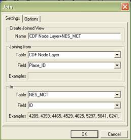
______ Make a CDF Node layer active. Then click ![]() to join CDF Node Layer to NES_CT where the
common fields are Place_ID in the Node layer and ID
in the NES_MCT.bin. (To open NES_MCT.bin,
just click the list named File Open… from the Table drop-down list under to,
which will lead you to a File Open dialog box).
to join CDF Node Layer to NES_CT where the
common fields are Place_ID in the Node layer and ID
in the NES_MCT.bin. (To open NES_MCT.bin,
just click the list named File Open… from the Table drop-down list under to,
which will lead you to a File Open dialog box).
![]()
______ When the dataview named CDF Node Layer+NES_MCT
is open, scroll all the way down to the records in the joined table to see if
they are joined.
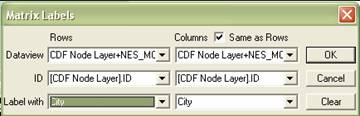
______ Choose Window-Matrix?-Shortest Path.
Then choose Matrix-Labels… Choose the Joined table from the Dataview, [CDF Node Layer].ID from the ID, and City from
the Label with drop-down list.
Practice #4 Make multiple routes
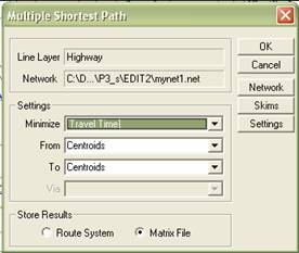
______ Choose Networks/Paths-Multiple Paths… where
you choose Centroids for From
drop-down list and Centroids for To drop-down list.
Make sure the active network is mynet1.
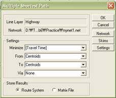
_____ In the Multiple Shortest Path dialog box, make
sure to check Route System under Store Results, then
click OK. Give a name myroute1.rts when Save As dialog box pops up.
![]()
![]()
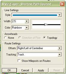
______ Display the topology of the resulting routes
by clicking ![]() (see the figure above). Hide this layer (Route)
not to clutter maps, also for the next practice.
(see the figure above). Hide this layer (Route)
not to clutter maps, also for the next practice.
Practice #5 Make one-way streets
Every line
layer contains a specific data field (called DIR) that TransCAD
uses to keep track of one-way streets. The field contains a zero when a link is
two-way. If the link is one-way, this field contains a 1 or -1. This practice
shows how to set up restriction to a certain directional flow in the selected
features of link layer.
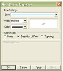
______ Make the Highway (line layer) an active
layer. Then click the Layer Style button ![]() on the toolbar.
on the toolbar.
______ Choose the Direction of Flow under
Arrowheads.

______ Make a selection set named US1 from the
Highway layer such that it meets the condition [Route 1]='U1'
AND Dir=0.
______ Choose Networks/Paths-Link
Directions… to display the Link Direction dialog box. Choose US1
for Mark drop-down list, and check the One Way Westbound under
Direction. (You can think of this new setting as the restriction to eastbound
travels in the
Practice #6 Cell-by-cell operation in matrix
In this practice, you will be evaluating the impact
due to the restriction to the eastbound travel in
______ Create a network from the entire features of Highway
layer where the field [Travel time] is chosen as the cost field. (Networks/Paths-Create…)
Give a name mynet2.net.
______ Create a travel time matrix
(Networks/Paths-Multiple Paths…) from Centroids to Centroids. Make sure the network setting is mynet2.net.
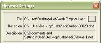
If you want to update the active network, simply
click the button marked below, and reload the network file in the Network
Settings dialog box (Network/Paths-Settings…).
![]()
A resulting travel time matrix should not be the
same as the travel time matrix you created in practice #3 because of an one-way restriction in US Route 1.
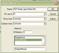
______ Make a Node Layer active. Then create a new
matrix file where its row and column should be Centroids, and
there are two matrices within the matrix file (to create a new matrix file, click ![]() , then
choose matrix ). Give a name mydelay.mtx
, then
choose matrix ). Give a name mydelay.mtx
______ When the empty
matrix is open, choose Matrix-Fill….
______ Click Cell by Cell tab. Check Subtract
matrices under Method, and choose Shortest Path for the first
matrix, then Shortest Path:1 for the second
matrix. (The first matrix stores the travel time with no one-way,
and the second matrix stores the travel time with one-way directionality in
US1. Thus the resulting matrix will contain how long it will be delayed by
having one-way directionality restriction). Click OK.
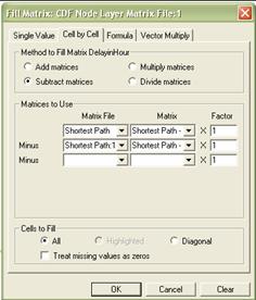
______ Choose DelayinMinute
from the drop-down list.
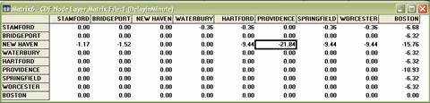
______ Choose Matrix-Fill.., then choose Formula
tab.
______ Choose [DelayinHour]
from the Matrix List drop-down list, and then type in *60. Click OK.
______ Label the matrix by the city name (see
Practice #3). The matrix shows that the travel from
Assignments (due at the beginning of next lab):
Copy
the directory H:\GEO520\Lab6\Assignment to your home directory. The
geographic file nhpn36029 is a highway layer, and landmark36029
is a point landmark layer in
Suppose
a new plan in Buffalo MPO (Metropolitan Planning Organization) is to convert
two-way
It is
assumed that all trips between landmark36029 (there are 5 sites) are made
through nhpn36029, and people take the shortest route to make a trip between
these landmarks. The centroid connectors between
landmark and highway should be created from the landmark to the closest node of
highways.
Submit
three matrices:
(1)
Before_Matrix: Distance
matrix between 5 landmarks before the plan
(2)
After_Matrix: Distance
matrix between 5 landmarks after the plan
(3)
Difference_Matrix: Difference
matrix that shows how longer the trip (in miles) will be due to the one-way
scheme
Make sure the matrices are labeled by the name of
landmarks.
Submit
two maps**:
(1)
Before_Route: Map showing
the multiple shortest paths between 5 landmarks before the plan
(2)
After_Route: Map showing
the multiple shortest paths between 5 landmarks after the plan.
* Use the condition LNAME = ‘
** When you create a layout, put the “before_route”
map at the top, and then the “after_route” map at the
bottom. In TransCAD, there is no live link between
map and layout – in other words, layout does not reflect changes in the map
after the map is placed in layout. That way, you can put together two route
maps created in sequence.